
Function of Plate & Shell Heat Exchangers
XPS – heat exchangers consist of two independent pressure sections:
- the plate side consists of a pack of round corrugated plates, which are alternately welded together on the circumference or on the two openings in the plates.
- the shell side is a cylindrical shell either fully welded, openable at one side or openable at both sides.
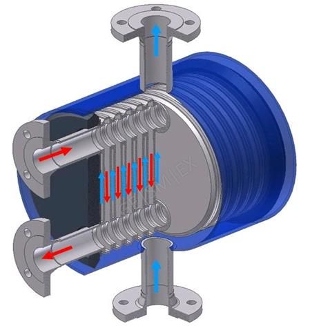
The gaps between the corrugated plates form flow channels, which primary and secondary media flow through alternately. Flow directors in the shell side prevent any bypass – flow between shell and plate pack, which reduces thermal performance.
The flow direction of both media can be arranged as counter-flow, co-current or cross-flow. The heat is transferred via the corrugated plates, which create turbulence and enhance heat transfer. When one or both media are evaporating or condensing partly or completely, it is called a two-phase application.
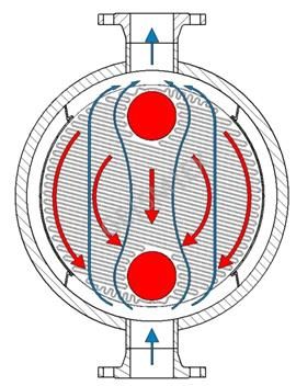
Counter flow
the most common form of flow configuration
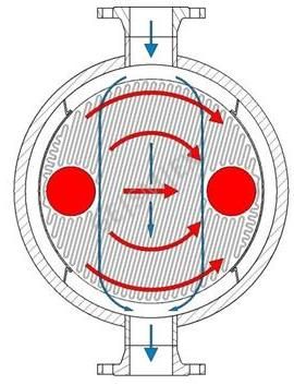
Cross flow
for a reduced resistance on the primary and secondary side

Co-current flow
for maximum temperature differences at the inlet, or to avoid temperature crossing
By means of deflections the plate and shell side can be configured for multi passes. This increases the thermal length.
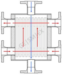
Inlet and outlet on both ends
For large volumetric flows on the plate side
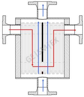
Plate side deflection
For large differences in volumetric flow rates between plate and shell side
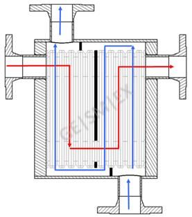
Shell and Plate side deflection
For optimizing the pressure loss and heat transfer on both sides
XPS plate heat exchangers are available in five sizes and with different corrugation patterns, i.e. with different corrugation angles and pressing depths.
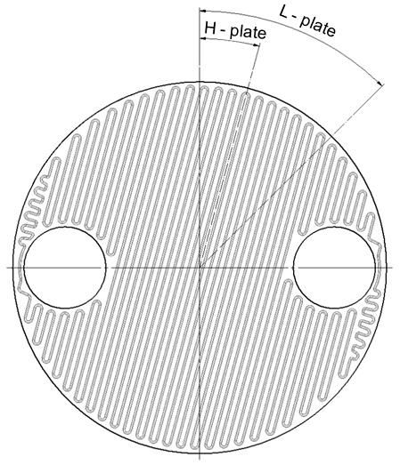
Plates with H-, L- and G-corrugation
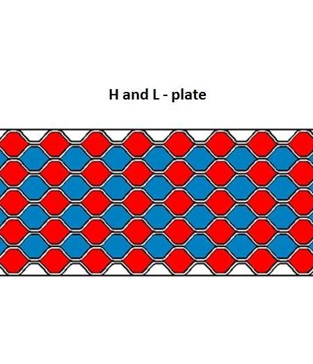
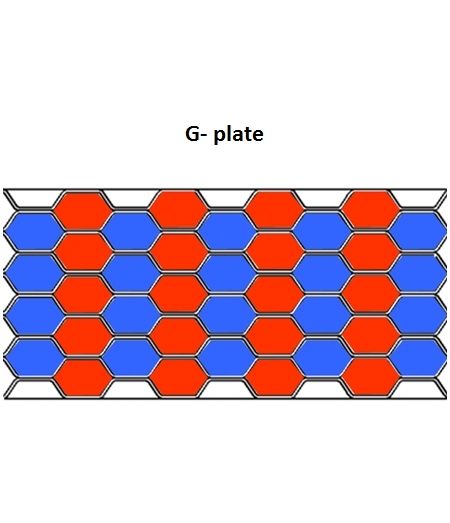
H-plates allow high heat transfer rates caused by a high turbulent flow. L-plates are used in applications which are optimized for a minimal pressure loss, or hydraulically limited. In gas / gas – applications or when the media is contaminated with solids G-plates are often used, which has a larger cross-sectional area.
Design data
-
Design pressure: -1 to 400bar
-
Design temperature: -196°C to +500°C
-
Plate material: 1.4404, Titan and Nickel alloys
-
Shell material: Carbon steel, Stainless steel, Titan, Nickel alloys
-
Nozzle sizes: DN25(1") to DN1000(40")